Three Pendulum Harmonograph
What is a harmonograph?
A harmonograph has at least two rigid pendulums with a pivot about one third of the way down. The bottom has a heavy weight, and the top is attached to a long, more or less, horizontal bar. The two pendulums are at right angles and arranged so that a pen is supported where the arms cross. The purpose is to enable patterns to be drawn as the pendulums swing to-and-fro. The image below the harmonograph in the current state of construction. Under that are some examples of the images formed with just the two pendulums being used.
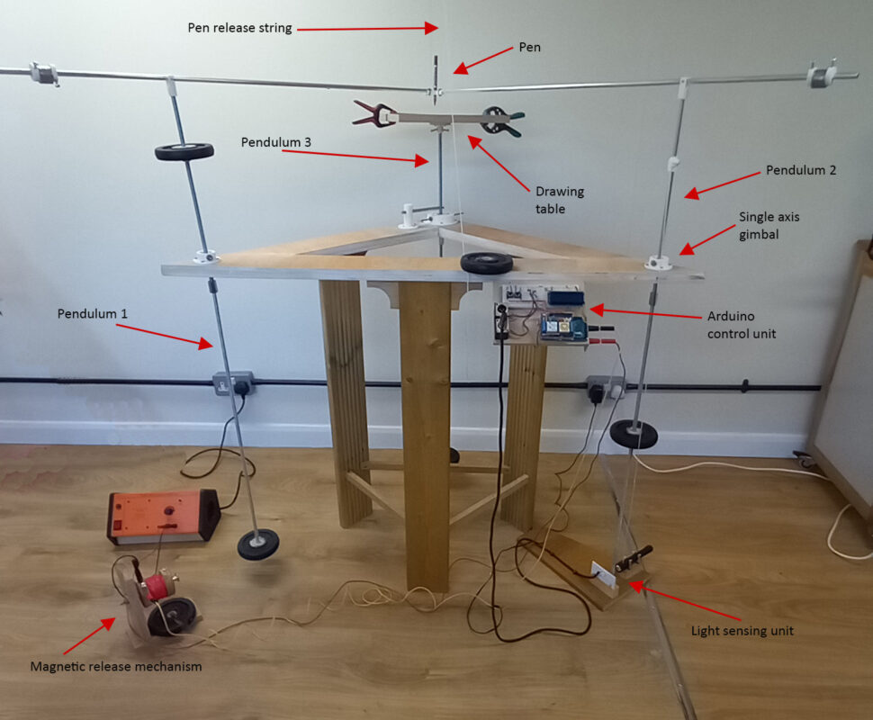
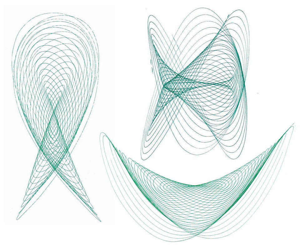
The basic frame is triangular and gimbals on the corners of the longest side are positioned so pendulums-1 and pendulum-2 can swing at right angles. The third pendulum supports the drawing table and can swing in two directions by means of a 2-axis gimbal with the axes at right angles.
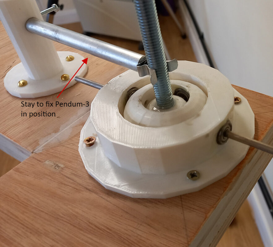
My grandson Milo and I jointly own a 3D printer and Milo designed the gimbals. The design allowed for very small ball races to be inserted to reduce the friction on the axes. The image below shows the 2-axis gimbal. It also shows the 3D printed “stay” which can hold pendulum-3 fixed so that the harmonograph can be first optimised just using two pendulums.
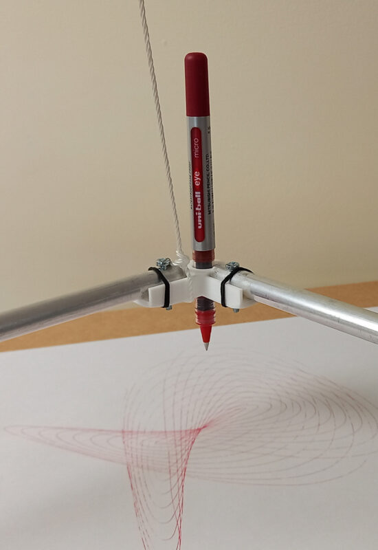
The top of each pendulum supports a (roughly) horizontal rod. The penholder is fixed at the point where they meet, just above the drawing table. A simple string mechanism holds the pen up until the pen movement has been started and it can then be lowered onto the paper. The balance weights on the horizontal arms are adjustable along the length of the arm so that the downward pressure from the pen is just enough to make a smooth line. Almost all the connections, balance weight holders etc were 3D printed. Here is the penholder.
To get interesting drawings the frequencies of the pendulums need to be is simple whole number ratios e.g. 2:3, 3:5 etc. To do this gym weights are used which can be moved along the length of the pendulum. Initially we did this with a smooth rod where weights were supported by a moveable bush underneath. It was difficult to tune this accurately, so the smooth rods were replaced with threaded rods. The centre hole in the weights had a nut fitted using a wood filler and glue to hold it in place. This allows the weight to be spun and so moved up and down the threaded rod.
We decided first to get the harmonograph tweaked with just two pendulums. This is where we are at the moment. When this is done we will get the third pendulum involved. To begin with we tried using a stopwatch to measure the time periods of the pendulums. This was tedious, so it seemed sense to use some electronics. This shows the Arduino unit that was developed.
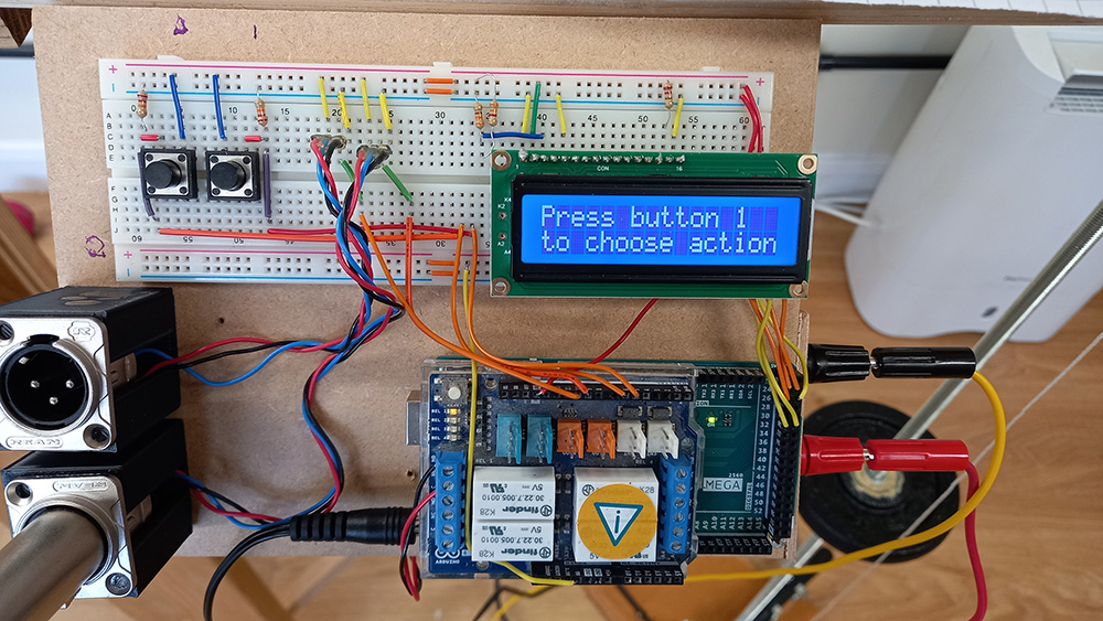
This was connected to two light sensing units, one for each pendulum. The pendulum swings through a gap between a torch and a phototransistor the latter being positioned at the end of a short narrow bore copper tube. The narrow tube was necessary to ensure accuracy. As the pendulum swings through the gap the light beam is cut off for a very short time and the resulting signal from the phototransistor is fed to the Arduino. Here is one of the two units.
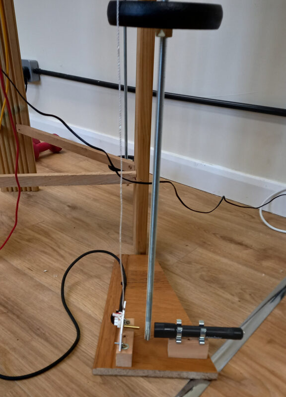
The code on the Arduino allowed the following procedure.
- Set the pendulums swinging.
- Press button 1 on the Arduino ready to time Pendulum-1.
- When OK Press button 2 and the Arduino measures the time of 5 complete swings to-and-fro and takes an average. This is displayed (no need to write this down – the Arduino remembers it.)
- Press button 1 again and this enables the other sensor on Pendulum-2.
- When Ok Press button 2. The Arduino then similarly times Pendulum-2 and when done it calculates the ratio of the two time periods and shows this on the LED display.
- The weight can then be adjusted up or down according to the result to get nearer to a whole number ratio. This may need doing a few times.
This worked well and allowed some good results with just the two pendulums. However:
The drawing also depends crucially on the phase difference between the pendulums. If one is released when the other is at the end of its swing, then the drawing is quite different from when one pendulum is released at the moment when the other is at the middle of its swing. There are a range of drawings possible according to the actual time when one is released in relation to the position of the other. It was found very hard to effect such releases by hand that would give a full range of possibilities.
To do this a third option was added to the Arduino button 1. One of the light sensing units was positioned by one pendulum. When the light was interrupted a relay on the Arduino board was opened releasing an electromagnet holding the other pendulum at the end of its swing. This meant that it is possible to position the light sensing unit at any point in the swing of one pendulum and release the other pendulum at that moment.
Here is the electromagnet that does this.
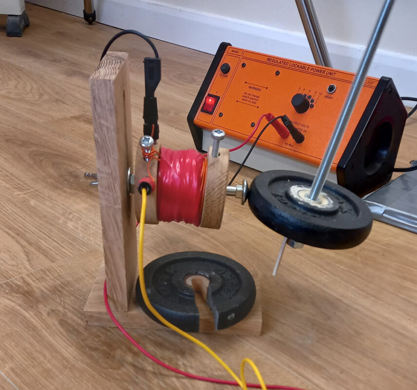
This is as far as we have currently got with the project. A small task remains to set a ruler against a pendulum to be able to set the light unit to be positioned at a known phase when releasing the electromagnet.
There is then the much bigger job of control and use of the third two axis pendulum holding the drawing table.
.